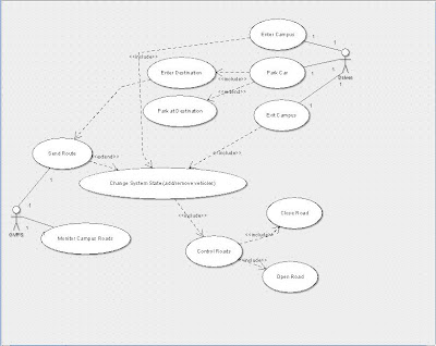
Hey Guys, here is the use case diagrams for the monitoring centre and the UML diagram jpg!
| Name: Campus Monitoring Center – Entering campus to Exit Includes: None Extends: None Normal Flow:
car is taken off the GVPS system map.
6.a Enters new destination, go back to step 1 6.b Proceeds to exit campus, system calculates route to exit as usual Abnormal Flow: 3.a Road obstruction is in the desired route – route is re calculated and the fastest alternate route is used taking into account speed limits 4.a Destination car park full – System finds nearest available car park and re routes |
| Name: Campus Monitoring Center – Calculate Route Includes: None Extends: None Post-conditions – Destination entered, Vehicle on campus Normal Flow:
Abnormal Flow: 3.a Driver takes wrong turn – system goes back to step 1 and assigns the fastest route to the in car system 3.b Road block created which blocks the current route – System goes to step 1 and re calculates a new route to avoid the road block. |
Cheers
James
No comments:
Post a Comment